Computer Applications - Project 1 : Building Modelling and Documentation

Ting Wen Yi / 0361799
Computer Applications/Bachelor of Design (Hons) in Creative Media
Project 1 : Building Modelling and Documentation
PROJECT 1 : BUILDING MODELLING AND DOCUMENTATION
This project requires us to develop a Revit model based on an architectural design of our choice, sourced from the internet. The model will be constructed using architectural components such as walls, roofs, stairs, floors, curtain walls, doors, and windows. Once completed, the model will serve as the basis for generating documentation drawings using Revit Architecture’s documentation tools, including sheets, title blocks, sections, room tags, schedules, and more.
Choosing the building (online)
When I was first selecting a house for this project, I was initially drawn to farmhouse-style designs because I liked the slanted roof and the overall warm, rustic feel of the architecture.


Figure 1.1.1 & 1.1.2 Barndominium


Building 4


Figure 1.4.1 & 1.4.2 Farmhouse H+M House
I chose this house as my model after spending a couple of days searching. I selected it because it includes detailed drawings, complete with specifications and elevations, unlike the other designs I found, which lacked sufficient technical information.
Problem Faced


Figure 1.5.1 &1.5.2 Grids & Walls
After placing all the grids and starting to build the walls, I realized a serious issue, the drawings were very complex, with too many overlapping elements, making them difficult to read. Since I took this module as a free elective, I found it quite challenging. I spent a few days trying to resolve the issues, but it became too time-consuming and overwhelming. Eventually, I decided to switch to a different house design that was much simpler and more manageable.
New House Option
 |
Figure 2.1 Simple House |
Later, I found a three-story house on SamHousePlans that had a much smaller land size and a simpler overall design, making it more suitable for the project.
Grid/Dimensions


Figure 2.2.1 & 2.2.2 Creating Grids Based on Drawings |
I started by creating the grid and guidelines. Since the drawings included all the dimension specifications, it was easy for me to place the guidelines accurately without needing to manually measure the grid spacing.
Creating Walls


Figure 2.3.1 - 2.3.3 Creating Walls on Grids |
After setting up the grid lines, I began placing the walls according to the reference drawings. Using Revit’s Wall tool, I selected suitable wall types and adjusted their heights and thicknesses based on the floor levels and section views provided in the drawings. In some areas, I customized the wall thicknesses to meet the design requirements and to better match the structure shown in the reference.
Creating Levels
 | |
|
Next, I created the building levels. The house has three main floor levels, but I noticed that the porch area and the stairs leading into the house are positioned 500mm below the first floor level. To accurately reflect this in the model, I created an additional level and named it "Ground Level" to represent the base elevation of the porch and entry steps, while keeping the first floor level for the main interior spaces.
Floor & Roof
 |
| Figure 2.5 Floor and Roof Progress |
After completing the walls, creating the floors was relatively straightforward. I used the Floor tool in Revit and followed the outline of the walls to define each floor slab accurately. The roof was also easy to construct since it was a small, flat roof without any slope or complex angles. Unlike pitched or slanted roofs, this flat roof required minimal adjustments, making the modeling process quicker and more efficient.
Stairs


Figure 2.6.1 & 2.6.2 Stair 1
The house design included two staircases. However, the default stair types in Revit didn’t match the design from my reference drawings. To resolve this, I created custom stairs using the Edit Sketch option. I watched a few simple YouTube tutorials to better understand how to draw and adjust stair sketches manually. Based on the reference dimensions, I successfully modeled the stairs to match the original design.


Figure 2.6.3 & 2.6.4 Stair 2
The only difference between the two staircases was that the staircase on the first level had two additional steps compared to the other. I adjusted the stair sketch accordingly to match the reference drawings and ensure the step count and height were accurate.
 |
Figure 2.6.5 Original Stairs Reference |
The original drawings did not include any railings, so I removed the default railings that Revit automatically placed.


Figure 2.6.6 & 2.6.7 Stair Exterior |
There is also a small two-step stair outside the house. To model this, I used the Floor tool to create each step as a separate slab. I then annotated the steps in the plan view.
Door Family


Figure 2.7.1 & 2.7.2 Door Family Progress
I followed the tutorial video to create a custom door family. Using the custom door family I created, I adjusted the width and height to match the specific dimensions I needed for the design.
Other Doors


Figure 2.7.3 & 2.7.4 Door (Other) Progress
For the other doors in the project, I used the default door templates available in Revit. I duplicated them and modified the dimensions to match the sizes required for my design.
Window Family


Figure 2.8.1 & 2.8.2 (Louvre) Window Family Progress
I followed the tutorial video to create a louvre window family that I could use in Project 1. Thanks to Mr. Koh’s guidance, the window is fully functional and can be adjusted to different sizes based on my needs. This allowed me to customize the window placement throughout the model while maintaining consistency with the original design.


Figure 2.8.3 & 2.8.4 (Other) Window Family Progress
I also created another custom window myself because the window frame had a unique design, with inconsistent spacing between the panes. Since it didn’t match any of the default window families, I modeled it manually to reflect the specific proportions and layout shown in the reference drawings.
 +
+
Figure 2.8.5 & 2.8.6 (Other) Window Family Progress (Plan View)
The custom window displayed an unusual box in the plan view, which didn’t appear in the 3D view. Since it wasn't part of the actual design, I hid it in the plan view to keep the drawings clean and accurate.


Figure 2.8.7 & 2.8.8 Window Mistake
My building includes several three-panel windows with equal-width panes. Initially, I used the Curtain Wall tool to create them because it was easy to make the panels equal using the EQ setting. However, I later realized that curtain walls are meant for larger glazing systems, not standard residential windows.

Figure 2.8.9 & 2.8.10 Corrected Window & Adjustment
So instead, I used a different window family that had three glass panels and resized it to match the required dimensions. This approach was more accurate and appropriate for the design.
 |
Figure 2.8.11 Window & Door Progress |
After placing all the doors and windows, the model started to look much more complete and realistic—more like an actual building.
Curtain Wall


Figure 2.9.1 & 2.9.2 Curtain Wall Progress |
The house design included only one curtain wall. I used the Curtain Wall tool in Revit to draw it according to the reference drawings. The curtain wall design featured one window panel and one door panel. To reflect this, I used the technique we learned in the tutorial by modifying individual panels to replace one panel with a door while keeping the other as a window. This allowed me to accurately match the original design.
Wall Openings
 | |
|
To create unique openings in the wall, I used the Wall Opening tool to design special cut-outs for certain walls.


Figure 2.10.2 & 2.10.3 Wall Openings for Window and Doors |
One of the window designs had a column positioned between two glass panels, so I used the Shaft Opening tool to create a vertical gap in the wall. Then, I placed two separate windows on either side of the opening to represent the design. Although it may not look exactly 100% like the original, I believe this method was the most effective way to capture the overall look and feel of the design.
Railings


Figure 2.11.1 & 2.11.2 Railing Progress
The balcony railing was straightforward to model using Revit’s Railing tool. However, the railing was split into two sections because part of the balcony was enclosed by a wall. To address this, I created two separate railings to fit around the wall section. I also adjusted the spacing between the metal balusters to closely mimic the design of the original railing from the reference drawings, ensuring better visual accuracy.
Special Structure (Extrusion)
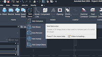


Figure 2.12.1 - 2.12.3 Void Extrusion
At the top of the balcony, there is a unique wall extrusion where one half is thicker than the other, and a rectangular recess is inserted between them. To model this, I created two walls with different thicknesses side by side. Then, I used a Void Extrusion to cut into the middle section, creating the recessed indent. This method allowed me to accurately replicate the special feature shown in the original design.


Figure 2.12.4 & 2.12.5 Extrusion & Void Extrusion (Balcony Wall Structure)
At the balcony, there is also a C-shaped structure. To create this, I used a combination of Extrusion to build the main form and Void Extrusion to carve out the inner space, shaping it into a clean C profile. This method allowed me to accurately represent the structure based on the reference design.
Roof Texture / Pattern


Figure 2.13.1 - 2.13.3 Roof Pattern
 |
Figure 2.13.4 Complete Building Structure |
After completing all the structural elements, the model was fully built. I then moved on to the next phase—preparing the documentation drawings.
Section & Callouts

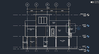
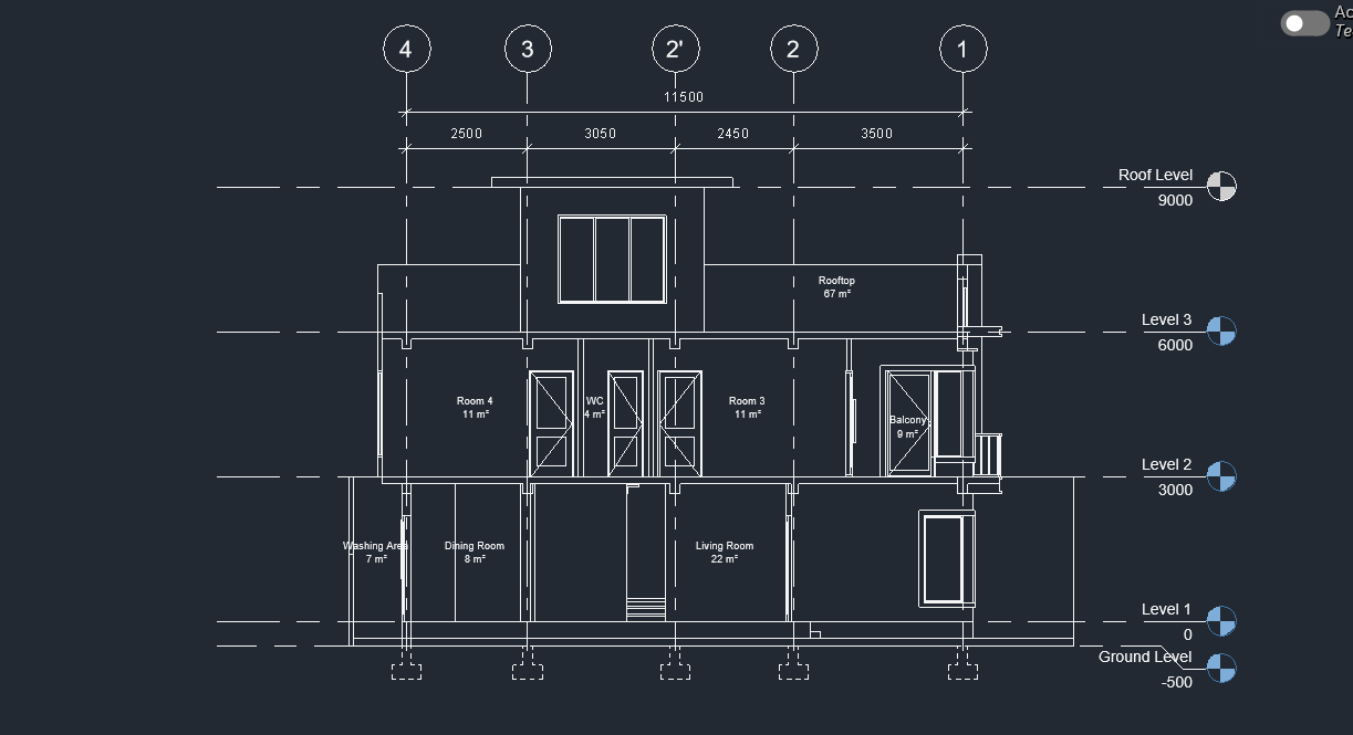 Figure 2.14.1 - 2.14.3 Sections
Although the brief only required two sections, I decided to create three because I felt the third section was important to show a cut through the center of the house, especially through the wall. This additional section helped provide a clearer understanding of the internal structure.


Figure 2.14.4 & 2.14.5 Callouts
I also created two callouts, one focusing on the door and the other on the window details. For the specifications in these callouts, I referred to online sources to ensure accuracy and to reflect realistic construction detailing.

Figure 2.14.6 Section Box
I also applied a section box to cut through the building in 3D view, allowing me to better visualize and present the internal spaces and structural layout.
Figure 2.14.1 - 2.14.3 Sections
Although the brief only required two sections, I decided to create three because I felt the third section was important to show a cut through the center of the house, especially through the wall. This additional section helped provide a clearer understanding of the internal structure.
Figure 2.14.4 & 2.14.5 Callouts
I also created two callouts, one focusing on the door and the other on the window details. For the specifications in these callouts, I referred to online sources to ensure accuracy and to reflect realistic construction detailing.
|
Figure 2.14.6 Section Box |
I also applied a section box to cut through the building in 3D view, allowing me to better visualize and present the internal spaces and structural layout.
Tag Room & Room Schedule
 |
Figure 2.15.1 Tag Room |
I used the Room Tag tool to label all the rooms in the model with their appropriate names.


Figure 2.15.2 - 2.15.4 Room Not Enclosed (Fixed) |


Figure 2.15.5 & 2.15.6 Room Schedule |
I organized the room schedule by sorting the rooms according to their levels first, followed by their names.
Beams & Footings


Figure 2.16.1 & 2.16.2 Beams
In the section drawings, the beams were not clearly shown or specified. To represent them in my model, I used the Cut Profile tool to manually draw the beams on each column within the section views.
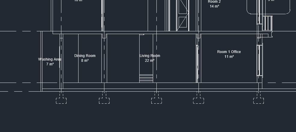 |
Figure 2.16.3 Footings |
I added the footings below the columns using dashed lines to indicate their position, following typical construction drawing standards. This helped provide a clearer understanding of the building’s structural base in the documentation.
Materials


 Figure 2.17.1 - 2.17.3 Applying Materials
Figure 2.17.1 - 2.17.3 Applying Materials
Lastly, I applied materials to the Revit model using the existing material library, modifying them to suit my design preferences. For some elements, I used Object Styles to assign materials, while for others, I applied individual materials manually. I tried to follow some of the original building’s color scheme, but for certain parts, I added my own ideas and personal preferences.
Exploded View & Sectional Perspective


Figure 2.18.1 & 2.18.2 Exploded View & Sectional Perspective
For both the exploded view and the sectional perspective, I followed the tutorial as a guide and adjusted the views to match my model.
Final Revit Documentation
 |
| Figure 3.1 Revit Documentation Progress |
After completing all the modeling and applying the materials, I began working on the documentation layout in Revit, following the methods Mr. Koh taught us during the tutorial. While setting up the sheets, I found that the default scale of 1:100 made the drawings appear too small, and 1:50 was too large to fit everything neatly on the page. So, I changed the drawing scale to 1:75, which provided a better balance between clarity and layout. I successfully organized the drawings and compiled them into a PDF for submission.
Figure 3.2 Final Revit Documentation (PDF)
REFLECTION
Experience
Taking on this Revit modeling project as a free elective was both a challenging and rewarding experience. At the beginning, I struggled to find a suitable architectural design that matched both my interest and technical skill level. I initially chose a more complex design but later switched to a simpler one after realizing the original choice was too time-consuming. Throughout the process, I learned to manage my time more efficiently and gained confidence in navigating Revit’s tools, especially in areas like creating custom families, managing levels, and applying materials. Despite some difficulties, particularly with unfamiliar elements like stairs and curtain walls, I enjoyed watching the model gradually come together.
Observation
One key observation I made during this project is how important it is to choose the right design at the start. A well-documented reference drawing makes a huge difference in modeling accuracy and workflow speed. I also realized that Revit’s default components often don’t match specific design needs, which led me to create custom families, such as the louvre window and special door types. The tutorial videos and in-class lessons by Mr. Koh were extremely helpful, especially for solving unique design challenges like creating voids, custom openings, and adjusting section views.
Findings
Through this project, I found that Revit is a powerful tool not just for 3D modeling, but also for producing detailed documentation. I learned how to properly use features like Room Tags, Schedules, Callouts, and Sections to represent architectural information clearly. I realized that even though I’m not from an architectural background, with the right approach and willingness to learn, I was able to successfully complete a detailed and functional building model.


Comments
Post a Comment